News Detail
The Importance of selecting the right Ferrite Core fort your Impeders in High Frequency Welding

The Importance of selecting the right Ferrite Core fort your Impeders in High Frequency Welding
Abstract
Impeders are commonly used in all ERW Tube Making lines. While experienced Mill operators pay attention to attributes such as Impeder Dimensions and Cooling, but enough attention is not paid to the most crucial aspect of the impeder – The Ferrite Cores. Also since impeders are not very costly for most tube sizes, often purchasers select the impeder and the Ferrite Cores by cost alone – compromising on efficiency and process up time. By means of this article, we wish to educate Tube Manufacturing Professionals about the importance of selecting the right grade of Ferrite Cores and their impact on Welding Quality, Impeder Life and Productivity.
Function of an Impeder
While producing ERW Tubes using a High Frequency Induction/Contact Welder – the Impeder plays a vital role in ensuring that the Heat is concentrated only at the seams of the formed strip for fusing when pushed by the Weld Rolls and not along the periphery of the strip (leading to the Tube turning Red Hot and thereby turning black in appearance with undesirable non-uniform hardness). The Impeder also concentrates the Flux of the Work Coil inside the Tube for more optimal power extraction and thereby increases the process efficiency.
In the absence of an impeder or in presence of a failed impeder – the entire tube will turn red hot. Physically speaking till the time Welder does not trip due to excessive current consumption – the Red Hot Tube when splashed with Mill Coolant would demonstrate undesirable hardness, improper welding and a burnt out blackish appearance. The Skin Effect conducting properties of High Frequency Currents ensures that current flows across the outer periphery of the conductor material and not along the entire cross section of the conductor material (which is the norm). The ERW Welding process exploits this principle of High Frequency currents to its advantage by creating a high resistance/impedance across the entire cross section of the conductor material. Current has the tendency of flowing across paths of least resistance – and thus flows across the edges of the Strip creating tremendous heat – sufficient to melt the strip edges – allowing the Tube Mill to fuse the formed tube together with the help of the Wed Rolls.
Types of Impeders
Impeders broadly are classified in 2 categories – Through Flow and Return Flow. Through Flow Impeders are the most commonly used design for a majority of Tube Welding Applications and also the cheapest. Return Flow Impeders are used for applications where the Tube ID has to be maintained dry for further processing such as Powder Coating or further coating. Depending on the Tube size impeders can further be classified as Cluster Impeders or Whole Impeders.
Construction of an Impeder
The construction of an Impeder has 3 components – 1) The Fibre Reinforced Epoxy Tube, 2) Ferrite Core(s) housed inside the Epoxy Tube and 3) Brass End Connector – to direct the flow of Mill Coolant inside the Impeder to ensure optimal cooling of the Ferrite Core(s).
The Fibre Reinforced Epoxy Tube is placed inside the Formed Tube and rests below the Welder Nose up till the Weld Roll Assembly. A rule of thumb is that the Length of the Impeder should at the very least be 2 x The Distance between the Work Coil Centre Point and the centre of the Weld Roll Assembly.
The Fibre Reinforced Epoxy Tube serves as protective housing for the Ferrite Core and also provides a path to the Mill Coolant to completely submerge the Ferrite Core on its way out to the end of the Impeder. In cases of inadequate support to the Impeder – the Fibre Reinforced Epoxy Tube also comes in to contact with the bottom portion of the Tube and yet protects the Ferrite Core from abrasion damage immediately though eventually the Ferrite core will get damaged once exposed. Therefore it is essential to choose the Epoxy Tubes of the right dimensions and thickness to ensure optimal performance of the impeder.
The Ferrite Core is a magnetic material comprising of oxides of Iron, Nickel, Manganese, Cobalt, Zinc and other additives baked at a high temperature and then crushed to a powder which is then mixed with binding materials and drawn through moulds of various shapes and dimensions. The drawn compound is dried and packed for dispatch.
Ferrites are available in different Geometries, Shapes, Sizes and lengths. Since most impeders are round – most Ferrite Cores are round as well. However, given the evolution in Tube Making Processes to direct Square/Rectangular forming – Ferrite Cores are made in Square and Rectangular Shapes as well.
Selection of the Ferrite Shape and Geometry depends on factors such as Impeder Design, Flow of Coolant, Impeder Mounting Arrangement & criticality of the welding operation, and the grade of the Weld Material.
Ferrites usually are quite inexpensive and therefore do not attract scrutiny while purchasing. This is unfortunate because the Ferrite Core alone contributes significantly to the efficiency of the Tube Welding process and also to the life of the Impeder. It must be appreciated that in case of an Impeder Failure – it can take up to 20 minutes to change an existing Impeder. Often – tube scrap is also generated in this process which further adds to the Process Cost. Given these high stakes, price alone should not be sole criterion for selection of the Ferrite Core.
So how then must an operator select a Ferrite Core?
Step 1: Identify the required Dimensions
The Impeder OD roughly should be no smaller than 0.80 * Tube ID
Once you have the Impeder OD, you can then reverse calculate the Diameter of the Reinforced Fibre Epoxy Tube.
Based on the Diameter of the Epoxy Tube – the thickness of the Epoxy Tube Can be selected. At the very least a 1mm Wall Thickness is preferred for smaller Diameter Impeders. The Epoxy Tube has to be strong enough to accommodate the weight of the Ferrite Core and durable enough withstand the installation of a Brass End Cap containing the plug for Mill Coolant Entry. At the same time, depending on the Impeder Mounting Arrangement and the available support – the Epoxy Tube has to be strong enough to withstand occasional/frequent abrasion from the bottom surface of the Steel Tube.
Once the dimensions of the Epoxy Tubes have been selected – select the Diameter of the potential Ferrite Core which can be inserted inside the Fiber Epoxy Tube. A minimum clearance of 1mm across the Diameter of the Ferrite Core should be available to properly insert the Ferrite Core inside the Epoxy Tube without damaging the wall of the Epoxy Tube. A broken Epoxy Tube can seep Coolant away from the Ferrite Core – sacrificing on cooling and prematurely crack/break exposing the Ferrite Core and eventually leading to impeder failure.
Step 2: Identify the required Geometry
Measure the size of the Mill Coolant Thread as available on the Impeder Mounting Assembly on your Tube Mill.
Refer to the drawings shared by your High Frequency Welder Supplier.
Hollow Ferrite Cores are most commonly used.

While, Hollow Ferrite Cores with Slots on the Circumference aid in cooling, but they also take away Ferrite Material from the top of the impeder and hence increase the distance between the Ferrite Material and Welding Seam.
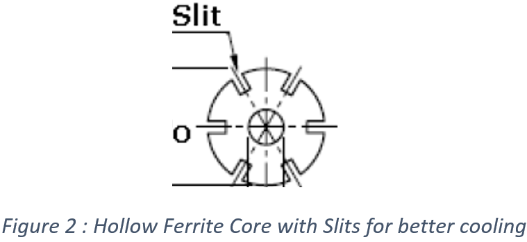
For Tube Diameters smaller than 1/2” – Round Hollow Ferrite Cores make more sense as even the slightest reduction of Ferrite Material to make a slot could affect the concentration of Flux.
For Tube Diameters larger than 3/4” – Round Slotted Ferrite Cores can improve the cooling tremendously and thereby extend the life of the Impeder.
For Cluster Impeders – a combination of Round Hollow, Round Slotted & even Solid Round Ferrite Cores can be used.
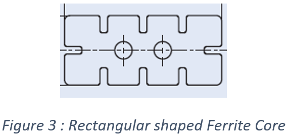
For Square & Rectangular Tubes being welded by Direct Forming Lines – Look for Square/Rectangular Ferrite Cores which can be placed in the most optimal orientation to give maximum surface area of Ferrite Material near the welding seam of the Tubes.
Step 3: Select the correct grade of Ferrite Material and not the cheapest cost
Flux Density: The primary function of the Ferrite Core is to be able to concentrate Flux from the Work Coil to the inner periphery of the Tube. This property can be measured in terms of Flux Density with a unit of measurement – Tesla. The higher the Flux Density of ferrite core the better it is. State of the Art High Frequency Welders can generate very high flux densities owing to their sheer power and superior design. The Ferrite Core therefore at the very least has to be designed to perform in such conditions.
Look for High Permeability. The higher the Magnetic Permeability the higher will be the magnetic Flux concentration. (Measured in absolute terms)
Curie temperature: The temperature below which a magnetic ferrite core becomes ferromagnetic in nature and above which it becomes paramagnetic. In simple terms it means the temperature above which the Ferrite Core will lose its magnetic properties permanently. Therefore the higher the Curie temperature – the longer will the Ferrite Core be able to retain its magnetic properties and thus function as a concentrator of flux and generator of impedance inside the Tube.
Core Losses:
the losses generated inside the Ferrite Core due to generation of an inefficient magnetic response to flux. A ferrite core rated for lower core loss will demonstrate better behaviour during high frequency welding and also contribute to more energy efficiency.
Now that you know the critical parameters of Ferrite Cores – look for a grade which demonstrates superiority in all or most of the parameters.
Make of the Ferrite Core: While making Ferrite Cores is not Rocket Science, but it is a process oriented product with strict requirements of Raw Material purity, adherence to heating cycles and proper testing.
One should strive for reputed makes with established use cases in the Impeder Application for High Frequency Tube Welding.
Seek extensive data sheets from your supplier. Ask them for their recommendation of the appropriate grade for your application. If you are not convinced with their recommendation – seek contact details of their clients and have a word with them asking about their experience with these Ferrite Cores.
Important Note about supplier data sheets: Please be sure to check that the data sheet shared by your supplier has values measured for Ferrite Cores for Impeder Application only. In case your supplier mentions that the values in his/her datasheet have been measured in Antennae/Magnetic Cores/Torroids/Transformer cores then these values might not be the most accurate or representative of the Core behaviour in Impeder Application. Be sure to check the data sheet mentions the grade of the Ferrite Core.
In case your supplier is unable to provide you with a data sheet – search online or look for alternates.
You must bear in mind that selection of the right Ferrite Core is imperative for your process efficiency. Try experimenting with different makes and grades of Ferrite Cores and tabulate your results and findings and then identify which make and grade works best for you.
There are several factors which can vary your experience. The operating frequency, design of work coil , number of turns in the Work Coil, Operating Temperature, Flow of coolant, Coolant temperature, the type of impurities and contaminants present in your Mill Coolant entering the Impeder, the grade of Steel Tube being welded, size selection and geometry and even mode of Welding – induction or contact.
Bear in mind that the high frequency welding process is a robust one. You will be able to get a welded tube even with many factors not being optimal – but your efficiency will surely suffer due to this. To optimise energy efficiency and increase Up Time & productivity it is essential to dwell on this subject with fair degree of seriousness.
Case Study from Data Available in the Market in June 2023
To prevent biases from creeping in, we have deliberately not mentioned the actual names of the suppliers. But this is actual data which we have collected from suppliers through their datasheets.
We also took their quotes for different grades over a variety of sizes to understand the difference in prices.
It was also amply evident and quite surprising to see the general lack of awareness in the suppliers’ distributors and channel partners about the presence of different grades or the significance of the various parameters as mentioned in the data sheet! (This could be a mere matter of chance due to geography)
However, when we spoke to a few of our clients, they too were not aware of the grade of the Ferrite Core being used by them. They could identify the makes of the Ferrite Core and the geometry though.
Let’s take a look at the below tables –
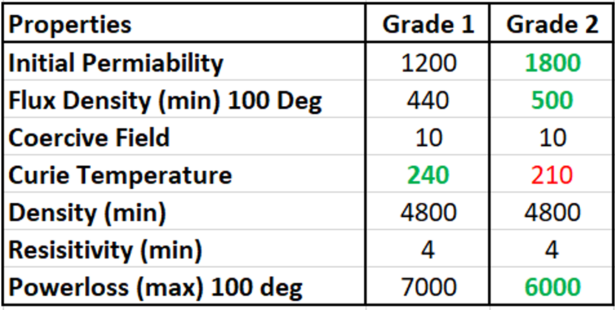
Datasheet of Reputed Supplier A:
The same supplier sells 2 grades of Ferrite Core Materials for the ERW Steel Tube Application. The difference in values of all parameters is quite evident.
Grade 2 does better than Grade 1 in 3 parameters (Initial Permeability, Flux Density and Power loss) but Grade 1 demonstrates a higher Curie temperature.
Between the 2, Grade 2 seems like a better choice and would outperform Grade 1 in terms of Impeder Life, Energy Efficiency and possibly Welding Quality as well.
Please note that the price difference in these 2 grades is not more than 20 %! Therefore, as an informed Tube Making Professional – you should certainly opt for Grade 2 and check for difference in performance. If the performance is indeed better (which in all likelihood will be the case) by investing an extra 20 % you have saved a lot more than your investment in the process.
On further probing, we were informed that there exists a 3rd Grade too which is even more superior. But since there is no demand for this grade – the manufacturer only produces this grade on a minimum order quantity. We were baffled by this piece of information.
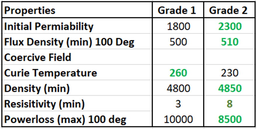
Datasheet of Reputed Supplier B:
The same supplier sells 2 grades of Ferrite Core Materials for the ERW Steel Tube Application. The difference in values of all parameters is quite evident.
However so, Grade 2 does better than Grade 1 in 3 parameters (Initial Permeability, Flux Density and Power loss) but Grade 1 demonstrates a higher Curie temperature.
Between the 2, Grade 2 seems like a better choice and would outperform Grade 1 in terms of Impeder Life, Energy Efficiency and possibly Welding Quality as well.
As in the case of Supplier A, the price difference in these 2 grades is not more than 20 %!
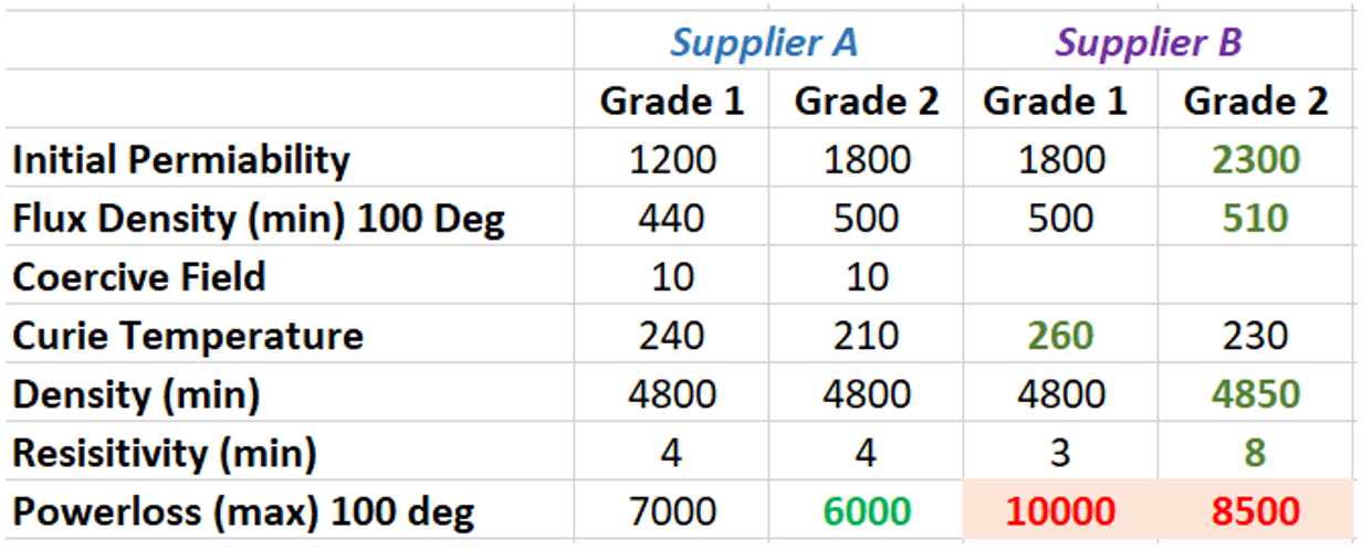
We can also pitch grades from different suppliers to see how they stand –
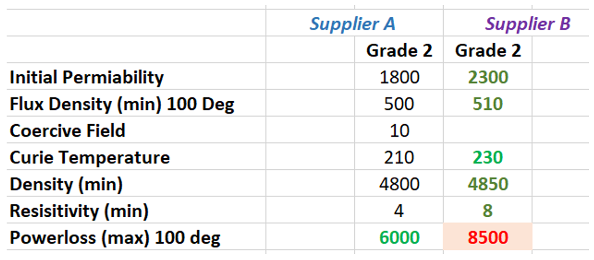
Since Grade 2 of both the suppliers were superior, let’s pitch them against each other to identify a prospective winner
The results here are surprising! It is quite evident that the parameters of Supplier B’s Best Grade beat those of Supplier A’s best grade by a large margin – but Supplier B states higher power loss!
This baffling observation really sent all the above theories in to thin air.
We then contacted Supplier B with our findings for their comment. Supplier B informed us that it was their policy to report the worst case scenarios for all parameters in their Data Sheets and assured us that their Grade 2 will give Supplier A’s Grade 2 by a huge margin.
Fun Fact: Supplier B’s Grade 2 is about 7 % cheaper than Supplier A’s Grade 2!
Conclusion: Price alone is no metric for selection of the most optimal Ferrite Core. You have to compare the parameters of the Ferrite Cores in totality while making a decision.
By spending an extra 15 % (in the above 2 examples) you are able to get benefits which will lead to far larger savings in terms of better weld quality, higher energy efficiency and higher Up Time !
Thanks for reading this.
If you need help in selecting the most optimal Ferrite Core/ Impeder for your Tube Welding Application, please drop us an email at info@unithermindia.com. Our experts will be happy to be of assistance to you.
Unitherm manufactures Impeders and Work Coils and sells Ferrite Cores for all applications. Feel free to send us your inquiries for a quote.
Disclaimer: The information presented above is to be used only as a reference. The intent of this article is to spread awareness and make Tube Making professionals aware of the significance of the Ferrite Cores and Impeders in the ERW process. The above information is not be used as advice but as mere guidance in selecting the correct Impeder. In the above article, Unitherm does not advocate any make or grade of Ferrite Cores to maintain the educational nature of this document.
Unitherm does not claim copyright of the above images. Images have been used from the internet for the sake of ease of identification by readers and for educational purpose only. Please contact us for removal of any images in case of violation of intellectual rights.
 14-06-2024